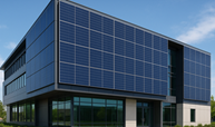
You can make your building itself earn electricity while serving as roof, façade, or window material—saving on construction costs and cutting operational energy use. Building-integrated photovoltaics (BIPV) replace conventional building elements with power-generating materials so your project delivers both shelter and on-site renewable energy.
This post Building Integrated Photovoltaics BIPV will show what BIPV systems are, how current technologies like semi‑transparent and bifacial modules work, and which design choices affect performance and cost. Expect clear guidance on integrating BIPV into real projects, from envelope detailing to system trade-offs, so you can decide whether it fits your goals and budget.
Fundamental Concepts and Technologies
This section explains the core materials, ways to integrate PV into building elements, and the electrical and performance traits you must consider when planning BIPV installations.
BIPV Materials and Product Types
You choose BIPV products based on appearance, structural role, and energy goals. Common materials include:
- Crystalline silicon modules: rigid, high-efficiency, suitable for roof tiles and façades where flat panels fit.
- Thin-film (CIGS, CdTe, amorphous silicon): lightweight and flexible, useful for curved façades and semi-structural cladding.
- Semi‑transparent and laminated glass PV: integrates into windows, skylights, and curtain walls while admitting daylight.
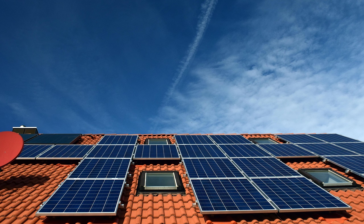
- BIPV roof tiles and shingles: replace conventional roofing materials and match building aesthetics.
Consider mechanical properties (wind, hail resistance), fire ratings, and edge-sealing details. You must also evaluate visual characteristics—color, translucency, and texture—because they affect occupant comfort and planning approvals.
Integration Methods With Architectural Elements
You plan integration either as direct replacements of building envelope components or as mounted systems that become architectural features.
- Replacement integration: PV modules act as roofing, façades, or glazing, so structural framing and weatherproofing must be designed for module loads and junctions.
- Attachment integration: modules mount on battens or support frames attached to the envelope; suitable for retrofits.
- Hybrid BIPV/T systems: combine PV with thermal capture (water or air) for combined electricity and heat output.
Detail flashing, thermal expansion joints, and drainage paths to prevent leaks. Coordinate with structural engineers for load transfer, and with façadists for fire compartmentation and maintenance access.
Electrical and Performance Characteristics
You size and specify electrical systems around expected irradiance, orientation, and system losses.
- Key metrics: module efficiency, temperature coefficient, STC and NOCT ratings, and module degradation rate.
- Balance-of-system components: inverters (string, microinverter, or DC optimizer), wiring, junction boxes, and monitoring hardware.
Account for shading and bifacial gain; façades and oblique angles reduce incident irradiance and change spectral response. Plan for system protection—rapid shutdown, grounding, and isolation for maintenance. Include performance modeling (hourly simulation) to predict yearly yield and payback under your local climate and building usage patterns.
Implementation and Design Considerations
You will need to balance site-specific solar resource, building orientation, and integration with structural and electrical systems. Prioritize durable materials, code compliance, and ease of maintenance to protect performance and warranty.
Key Factors in System Design
Evaluate solar irradiation on the façade or roof using on-site measurements or satellite data; aim for locations with at least 3–4 peak sun hours for meaningful generation. Select module type (glass-glass, thin-film, or crystalline) based on transparency, weight, and fire rating requirements.
Consider electrical layout early: string vs. module-level power electronics (microinverters/optimizers) affects shading tolerance and monitoring granularity. Plan array tilt and azimuth for façades or sloped roofs; small deviations can change annual yield by 5–20% depending on location.
Integrate with the building envelope: ensure thermal, waterproofing, and wind-load details meet local codes. Coordinate with structural engineers for load paths, ballast, and anchorage; lightweight systems may still require reinforcement. Specify clear O&M access, snow-shedding strategies, and module replacement paths.
Installation Challenges and Solutions
Weatherproofing interfaces often cause leaks when installers treat BIPV like conventional cladding. Use certified flashing systems and continuous air/vapor barriers; involve façade specialists during mock-ups.
Mechanical fastening and sealant longevity are frequent failure points. Specify stainless steel anchors, tested fastener patterns, and long-term compatible sealants to resist thermal cycling.
Electrical integration can conflict with fire egress or elevator rooms. Route DC wiring to minimize shading and maintain clearances; follow local fire codes for rapid shutdown and labeling. For complex façades, use pre-fabricated modular frames and on-site tested plug-and-play electrical harnesses to shorten installation time and reduce error rates.
Cost Analysis and Return on Investment
Calculate total installed cost including materials, structural reinforcement, electrical balance-of-system, and professional fees. BIPV materials cost typically exceeds conventional PV plus cladding, but you offset by eliminating separate façade or roofing material costs. Break down costs per m² and per kWh to compare scenarios.
Estimate energy yield with PVsyst or HelioScope and include degradation (0.5–1%/yr) and inverter/MLPE lifetimes. Account for incentives, tax credits, and any green building value premiums in lifecycle cash flow. Use a 20–25 year horizon for conservative payback; incorporate maintenance (cleaning, inspections, module replacement) and potential replacement of inverters at year 10–15.